I was finally able to find time this week to install the CAPI ACA and Booster board. There were a few items to take into consideration with changing the master summing circuit:
– The MCI has 10K summing resistors and the CAPI ACA is setup for 47K summing resistors. Therefore I had to adjust the feedback resistor and corresponding capacitor for the 10K resistors.
– I needed to circumvent a couple substantial parts of the master module and wanted to do so without hindering going back to stock. See notated schematic below.
– Where would I mount the board? I needed it to be close to the master module so the cable runs would be short.
– I wanted to tap into the Master L&R patch insert and send a balanced signal.
– Would it possible or necessary to leverage the mute function?
For the CAPI board, I’m leveraging 4 Quad Eight AM10 style opamps built to the 2520 form factor, 2 2623 Litz Output Transformers in the ACA section and Sphere / Quad Eight 75121 transformers for the booster.


First, I wanted to mount the board to accurately measure the cable lengths without having to guess. There happened to be a blank panel with a enough space and it could easily be mounted next to the patch bay. The patch bay section can be lifted up easily after removing five screws, making it much easier to drill holes. Now that it’s in place, let’s figure out how to route the signal.

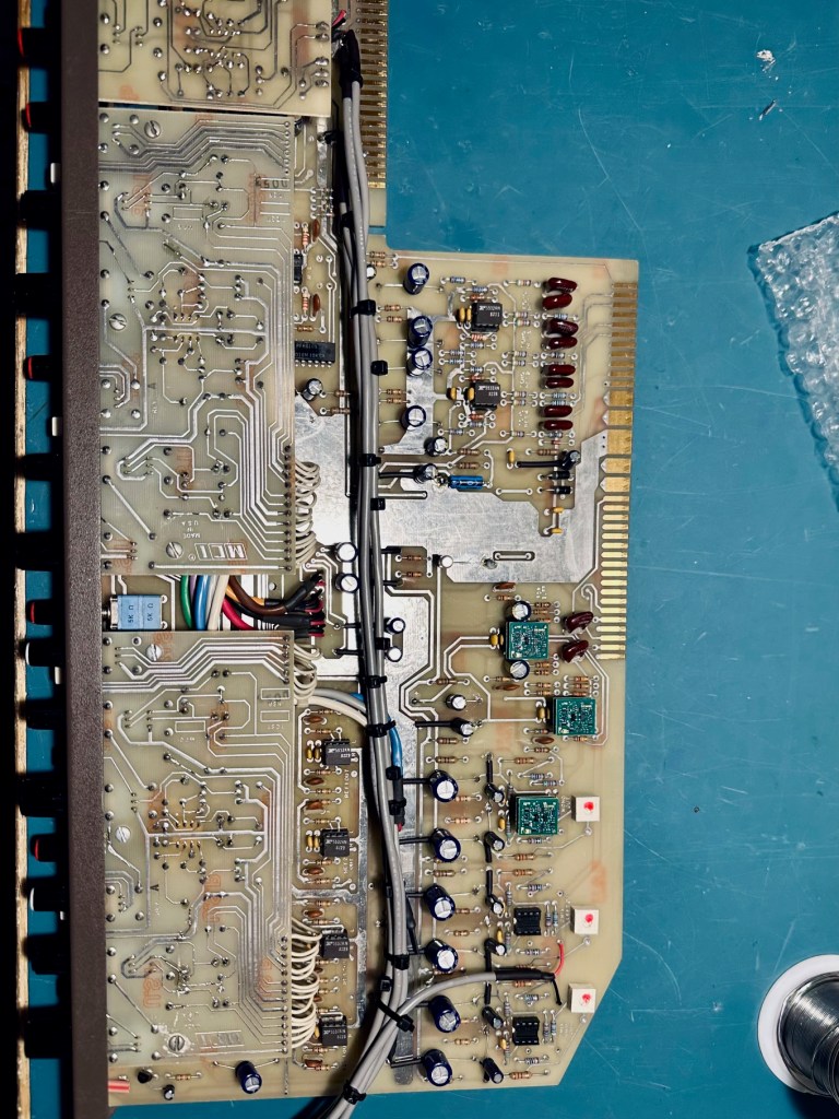
For the master module, I was able to remove a couple of components and splice into the circuit with ease. For the ACA input, I removed C1201 and C1401, and for the ACA shield, I removed R1202 and R1402. This allowed me to tap into the signal at these points and run a shielded cable to the new ACA board. For the ACA output, I removed the bottom belly pan and found the cabling that routed directly to the patch bay. I rerouted this up through the base of the bottom plain to the output of the new ACA board.
Next, I replaced the main output section. Fortunately, there were also a few easy component removals here. I removed R1802, R1902, R2002, and R2101 to isolate the signal for the booster inputs. I ran a shielded cable from there to the booster inputs on the ACA board. Finally, the output pins on the master module already had cabling running to the original master section. I simply removed those two cables and patched my boost output directly to pins 22, 23, 24, and 25 on the master module.
Final step was to get all the molex connectors installed, run power (+-18vdc) and fire it up. Everything fit snuggly and sounded great up power up!

After some listening tests, I’m overjoyed with the sound. It’s substantially better than the stock summing and booster. Mixes feel thicker and more well rounded. After spending 5 -6 hours and roughly $300, the upgrade was a great investment and I’d highly recommend it.
The last outstanding item is the mute function. Upon testing, the control voltage for the FETs on the CAPI board function the opposite of the MCIs topology. I’m going to explored enabling this feature over the next couple weeks as it’ll take some additional circuitry.
*** The CAPI ACA thread on GroupDIY and specifically Brian Roth were super helpful in validating the approach.

Leave a comment