Hello, everyone! I’m back today with part two. First, I’d like to thank you all for the positive feedback. If you have any questions about these articles or building your own Gates SA-70, please leave a comment or reach out via email or Instagram.
Lets tackle the additional features of our builds.
- Direct Input (DI)
- Adding a DI is relatively easy. You can add a 1/4″ jack to a SPDT switch or leverage a switched jack like the Switchcraft 12A. I typically used the 12A jack.
- The DI comes after the input transformer and before the input of the tube grid. The output of the transformer “7” would run to the input of the switched jack and the output of the jack would run to pin 4 of the 6SJ7 in the below scenario. On a 6J7 the output of the jack would run to the grid cap. I typically also use a 1M ohm resistor across the DI input and ground.

- VU Meter
- For the VU meter I try to leverage a vintage style meter with an internal diode bridge. This helps avoid adding an additional meter driver circuit and worrying about additional voltages. Honestly, it’s also because I’m lazy. Haha.
- I add the meter on a DPDT switch so it can be switched in and out of the circuit. Vintage type VU meters with an internal diode bridge will add harmonic distortion, which may or may not be wanted.
- To wire: I run a shielded cable from the output XLR to the DPDT switch and from the output of the switch to the meter. The down position will be “in circuit” and the up position “out of circuit.”
- Negative Feedback Control
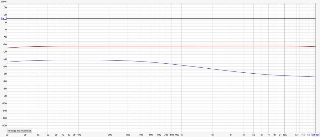
- The negative feedback control is a 250k ohm linear pot that adjusts the amount of negative feedback in the circuit. This will affect gain and frequency response of the preamp. One end brings out the high frequencies and the most gain while the other end of the pot reduces high end and lowers gain. You can see a frequency response graph below showing the two extremes of the pot.
*10k ohm resistor is required to keep the circuit stable.
- The negative feedback control is a 250k ohm linear pot that adjusts the amount of negative feedback in the circuit. This will affect gain and frequency response of the preamp. One end brings out the high frequencies and the most gain while the other end of the pot reduces high end and lowers gain. You can see a frequency response graph below showing the two extremes of the pot.

- Switchable Bass Control
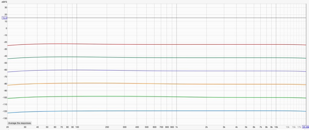
- This control is really quite subtle. It’s changing the value of capacitance in the feedback loop. I leverage a 6 position 2 pole switch that includes one position with no capacitor. Make sure the switch is “make before break.”
- The 5 capacitor values are as follows:
- .001 uf
- .0022 uf
- .0056 uf
- .008 uf
- .01 uf
- Below are examples of the 6 settings and their impact on the frequency responses.

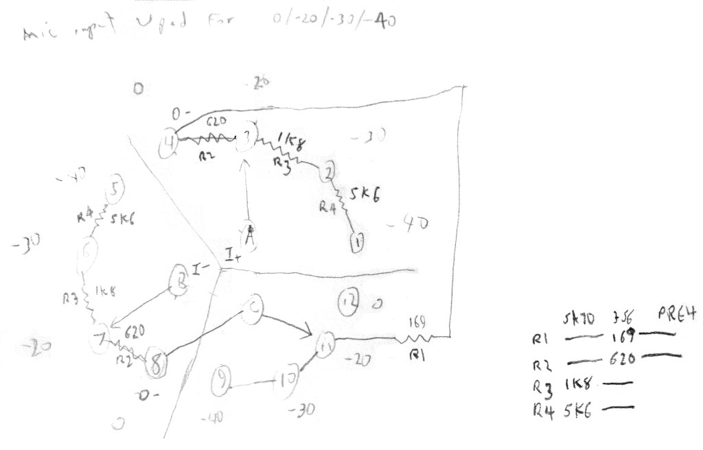
- Input Pad
- I use a borrowed design from EMRR (Doug Williams) on GroupDIY. He’s a great resource and helpful community member.
- The design is built on a 4 position 3 pole switch and allows for the following pad values: -40db / -30db / -20db/ 0db
- I love this pad because it allows for loud sources and to run line-level signals.
One thing to call out; the pad, gain, negative feedback and bass control all interplay with one another. There are many different variations in sound possible. That’s why I love this preamp!
I think that wraps it up for today. When I start a new build, I’ll make a part three showing how I lay out the faceplate and enclosure, drill holes, paint and assemble. I’m hoping to either prepare a video or have step-by-step pictures.
Thanks for reading!

Leave a comment