
Hello, friends!
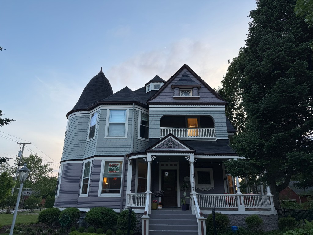
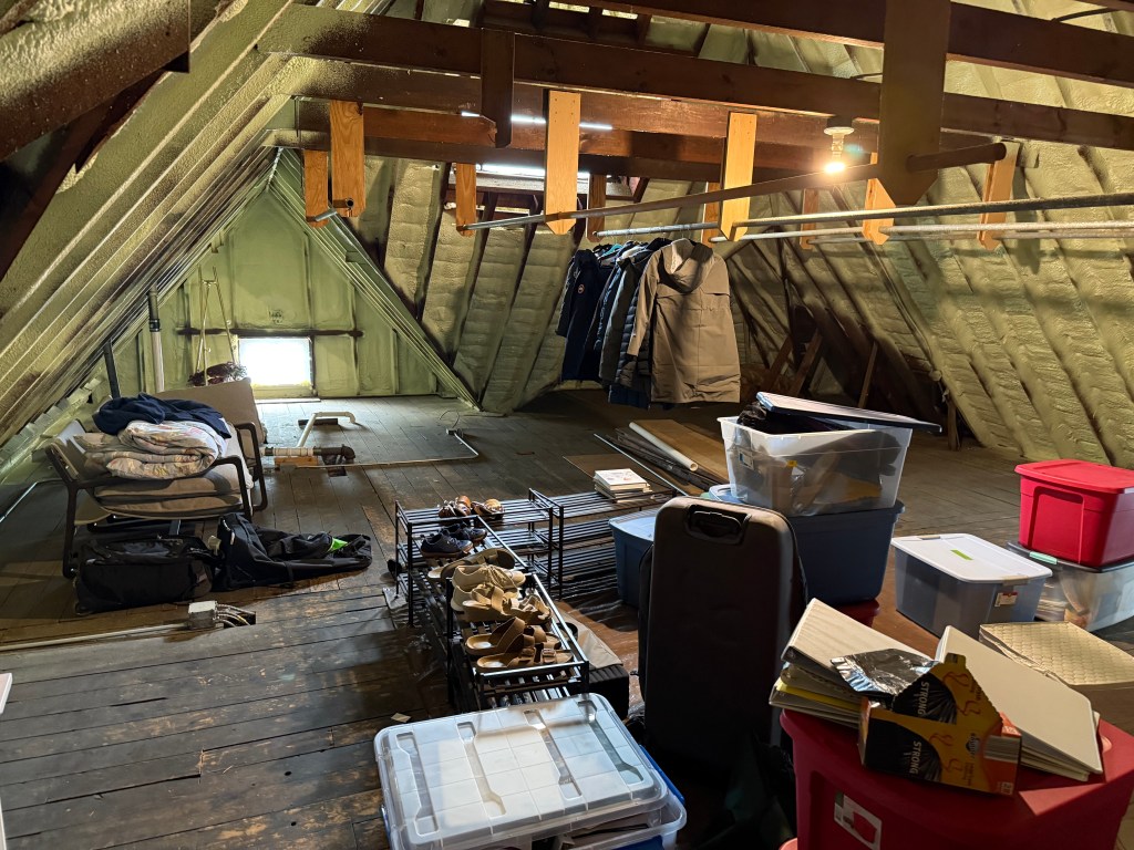
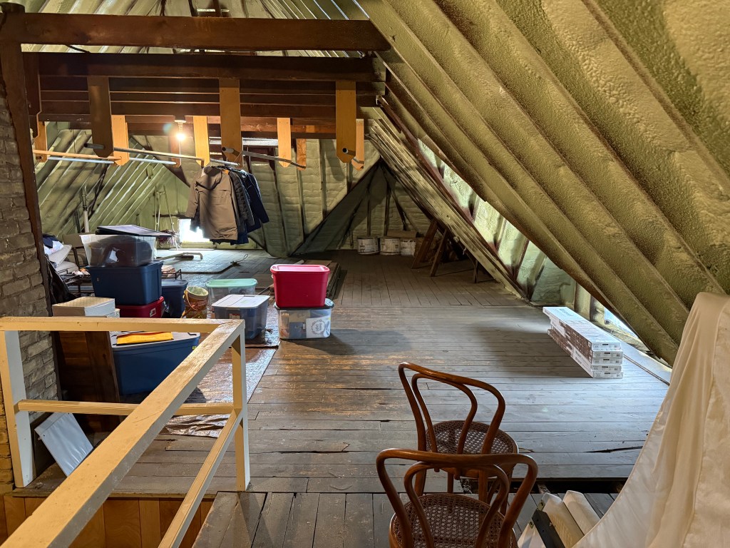
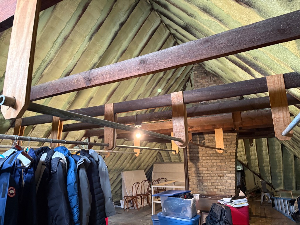
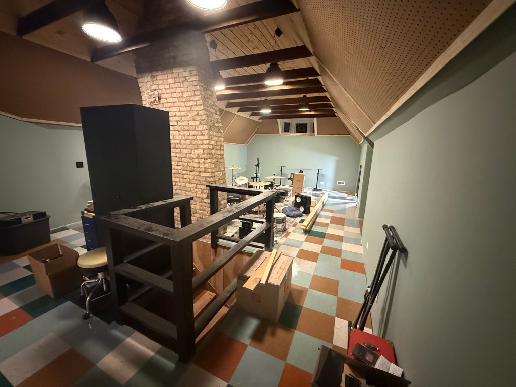
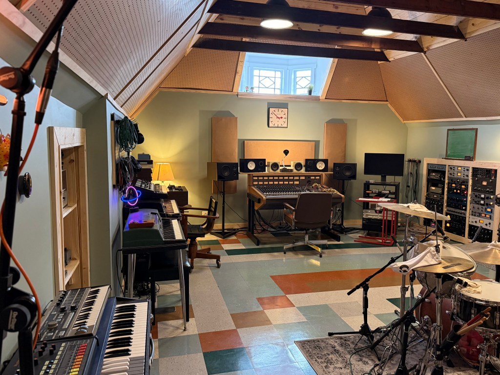
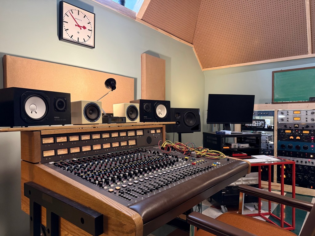
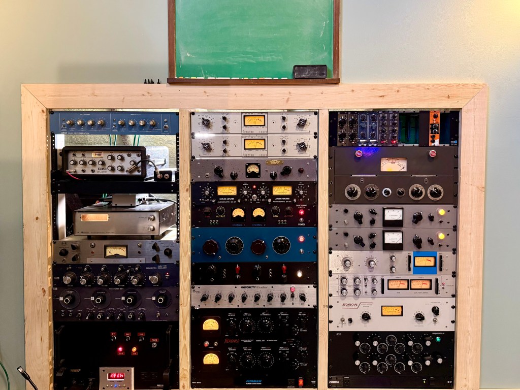
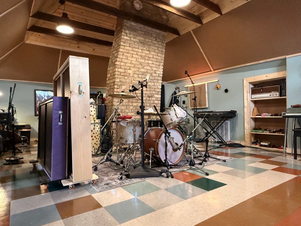
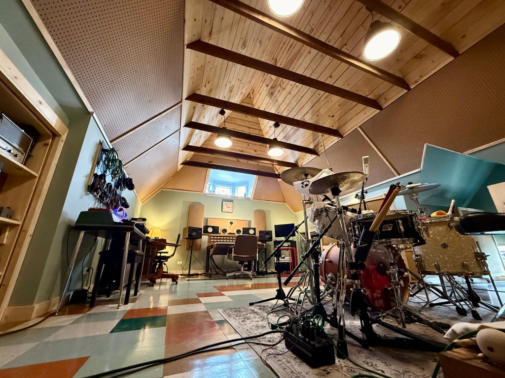
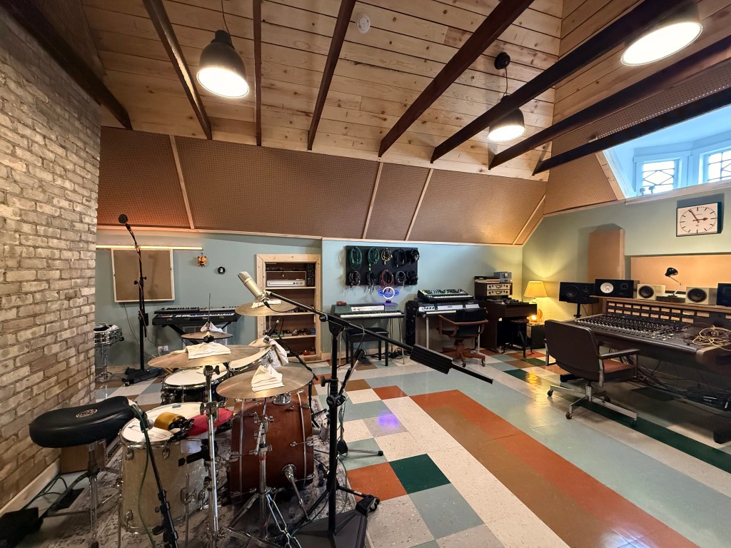
It’s been a while since I’ve posted, so I wanted to share a quick update. We’re now fully settled into our new home in Elgin, Illinois, and we spent much of the past year building, wiring, and preparing the new home studio.
During that time, I slowed down a bit on building and posting, but I’ve still had the opportunity to take on some really cool repairs and acquire some unique pieces of gear. Over the next few months, I’m excited to start experimenting with new projects, continue developing my PCB design skills, and begin offering more affordable gear for you all.
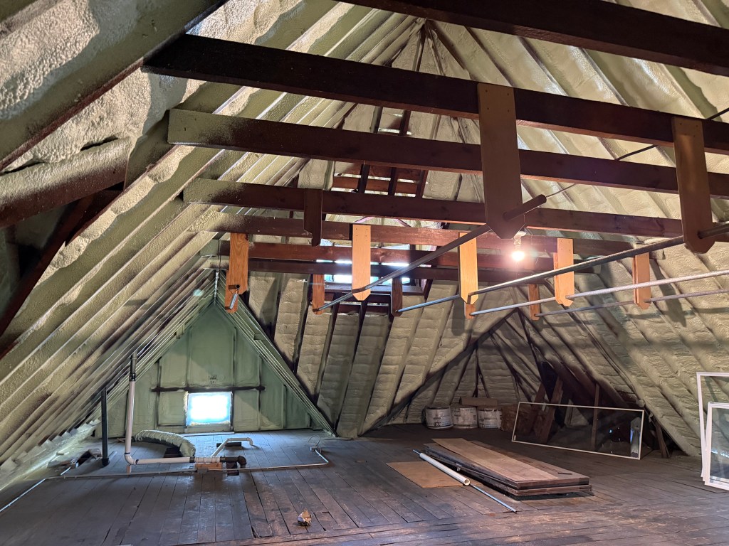
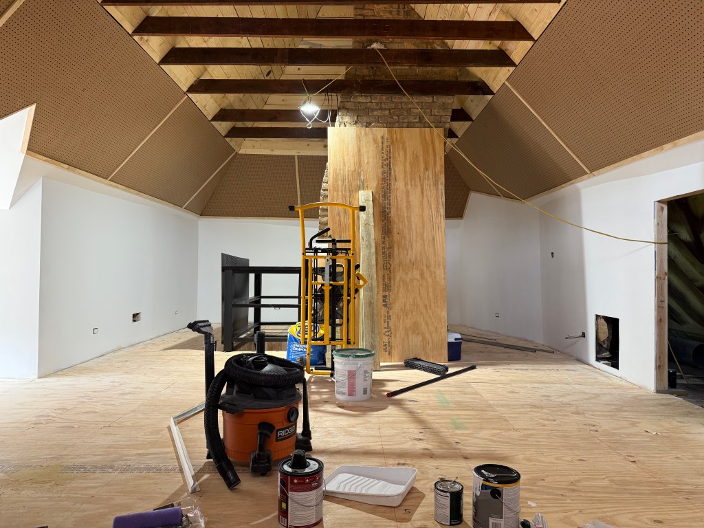
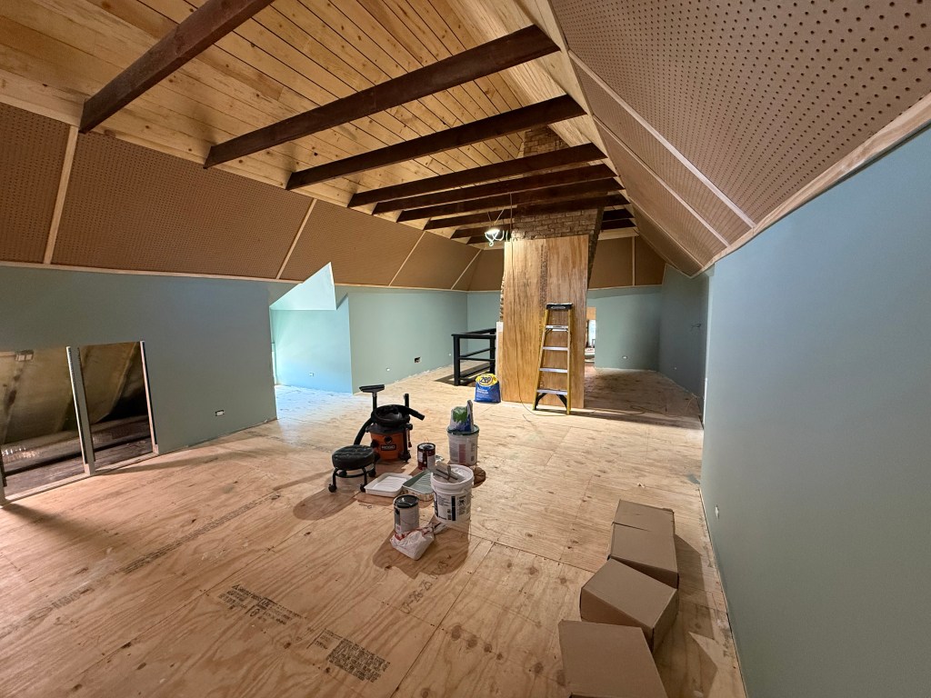
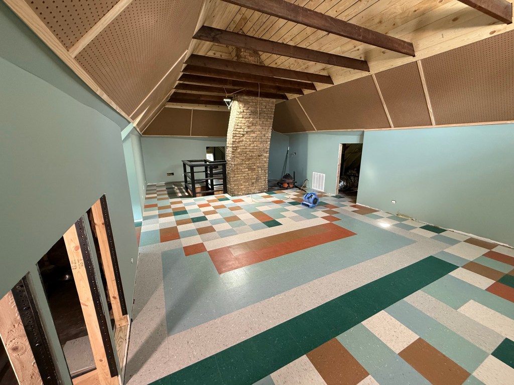
Here are a few photos from the studio build-out:

Today, I also wanted to share some information and insight into three new PCBs I’ve designed. After testing is complete, I plan to offer them as bare or populated PCBs, as well as fully finished builds. Two of these are completely new designs, while the third is based on a vintage RCA circuit. All of the designs I’m sharing today will require an off-board power supply, input and output transformers, and any desired input, gain, or level controls.
All of the designs I’m sharing today will require an off-board power supply, input and output transformers, and any desired input, gain, or level controls.
First up is the RCA design.
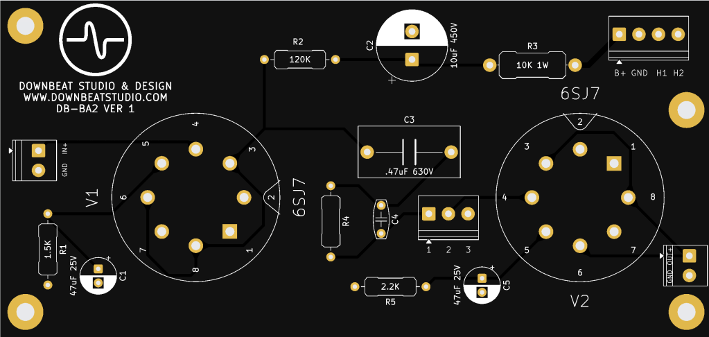
I’ve received quite a few requests for an RCA BA-2 preamp PCB, and I’m hoping this design will help fill that need. I stayed close to the original circuit but chose to use 6SJ7 tubes instead of 6J7s. For me, this change came down to tube availability, cost, and ease of construction.
The PCB can be mounted either vertically or horizontally, allowing it to fit into a 2U or 3U enclosure depending on your needs. The rest of the circuit remains nearly identical to the original BA-2C schematic.
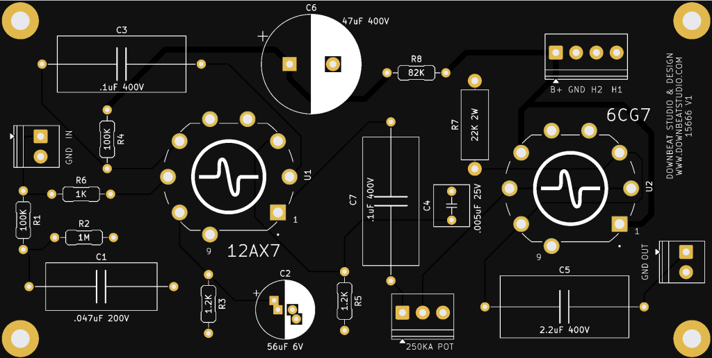
Next up is an Altec 1566/1567-inspired design.
I’ve always been a fan of the Altec 1567, but I’ve never had a need for an entire mixer. Earlier in my career, I tried using the 1566 as an alternative, but I never felt that it captured the same character or vibe as the 1567.
The goal of this design is to combine the input and output sections of the 1567 into a single-channel microphone preamp. The choice of transformers will have a significant impact on the overall sound, but I’m hoping this design gets closer to the character of the original 1567.
It’s a fairly straightforward circuit, with a 12AX7 tube in the input stage and a 6CG7 in the output stage. Like the RCA PCB, this board is designed to be mounted either horizontally or vertically. It should make it relatively easy to build a two-channel preamp in a 2U enclosure.
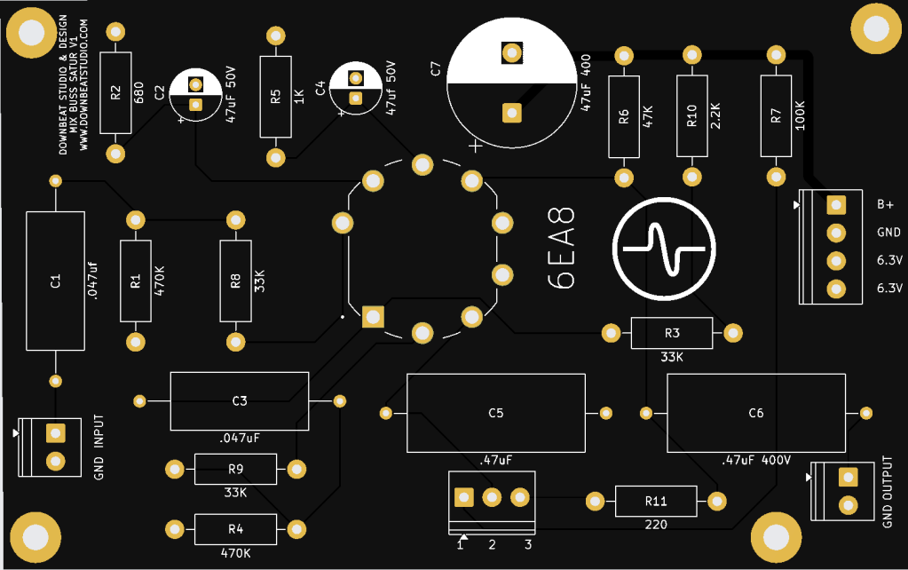
Finally, we have a tube-based bus saturator.
This design started with a large lot of tubes I won at auction—specifically, the 6EA8. The 6EA8 is a compact nine-pin tube containing a sharp-cutoff pentode and a medium-mu triode in a single envelope. Originally designed for television RF/IF and oscillator circuits, it can also work well in audio applications, with the pentode providing high gain and the triode serving as a driver, phase inverter, or output stage.
The goal of this design is to provide makeup gain and tube saturation for a stereo mix coming from a DAW or solid-state mixer. This is one of my first complete designs built from the ground up, so I’m sure there will be mistakes and plenty of iterations along the way.
The 6EA8 is inexpensive and readily available, which played a major role in the design choice. Fingers crossed it also sounds good.
I’ll continue posting updates as I test and refine these designs. I hope sharing the process helps demystify tube-circuit and PCB design, especially as I continue learning myself. Please feel free to interact and leave any questions in the comments.
– James


Leave a Reply