
Introducing the DB-15666: An Altec-Inspired Tube Microphone Preamp
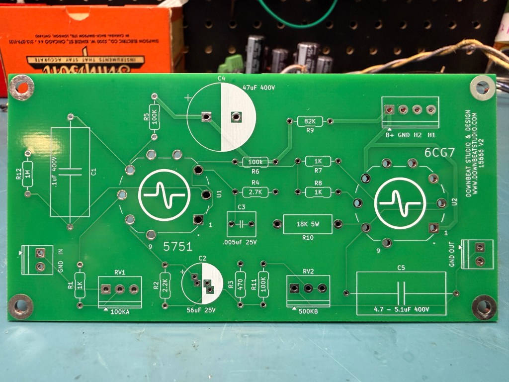
First off, I want to thank everyone who continues to read the blog, reach out with questions and support what I’m doing here at Downbeat Studio & Design. One of my favorite things about the DIY audio community is the willingness to share knowledge and ideas, and I hope these projects inspire others to experiment and build something of their own.
Over the past several months, I’ve been developing a handful of PCB designs inspired by some of my favorite vintage recording equipment. I’m excited to finally start sharing them, beginning with what I’m calling the DB-15666, a two-tube microphone preamp inspired by the Altec Lansing 1566A and 1567A.
Developing the DB-15666
I’ve always had a soft spot for vintage Altec equipment. My goal with this project was to combine elements of the 1566A and 1567A circuits into a standalone microphone preamp while adding some flexibility in how the circuit could be used and voiced.
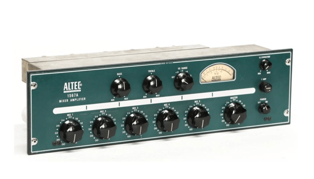
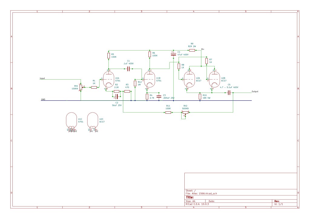
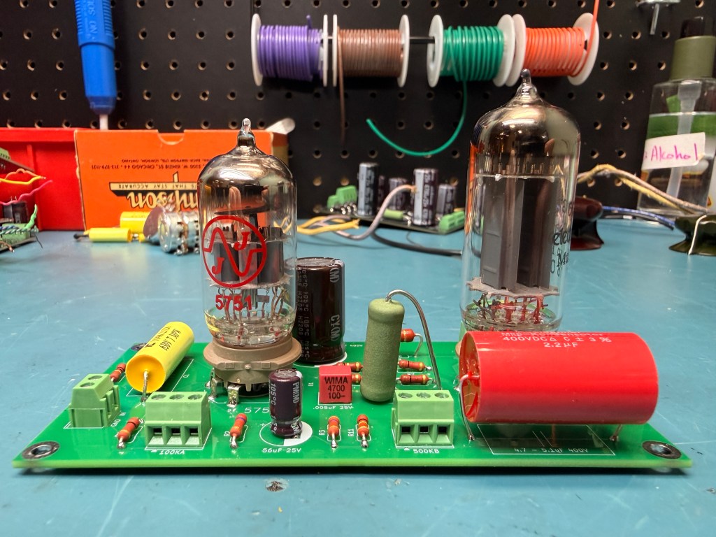
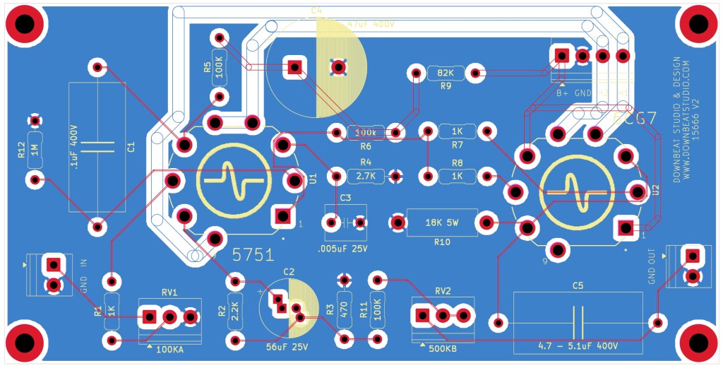
The DB-15666 utilizes a 5751 dual triode for two stages of voltage amplification, followed by a 6CG7 configured as a parallel cathode follower. The 6CG7 provides a lower output impedance and the current-driving capability needed to drive a suitable output transformer.
I intentionally kept both transformers and the power supply off the PCB, allowing builders to experiment with different components and configurations.
As with most DIY projects, the first build required some troubleshooting. Initially, I experienced low gain and a thin, distorted output. After revisiting the operating voltages and cathode follower biasing, I arrived at the current revision, which I’m really happy with.
View or download the DB-15666 schematic (PDF)
Input Drive and Negative Feedback
One of the things that makes the DB-15666 particularly fun is the interaction between its two controls.
Input Drive — 100k Audio Potentiometer
The input control sits between the microphone input transformer and the first tube stage. Rather than changing the amplification factor of the circuit, it controls how much signal is being fed into it. This allows you to drive the tubes harder for additional coloration and saturation or back things off for a cleaner sound.
Negative Feedback — 500k Linear Potentiometer
The second control adjusts the amount of negative feedback applied to the amplifier.
- More feedback produces lower gain, less distortion and a cleaner, more controlled broadcast-style sound.
- Less feedback produces higher gain and allows more of the circuit’s natural harmonic character to come through.
Between these two controls, the DB-15666 can go from a relatively clean vintage preamp to something with considerably more attitude. Adding an external output attenuator is another option for those looking to push the circuit harder.
Tube Selection
I originally developed the circuit around the 5751, but one of the first things I did after getting the preamp running was swap it for a 12AX7. I’m happy to report that it works great, and I really enjoy the additional grit it provides.
| Tube | Amplification factor (µ) | Character / potential use |
|---|---|---|
| 5751 | 70 | Original design, balanced vintage character |
| 12AX7 / ECC83 | 100 | Higher gain, additional grit and saturation |
| 7025 | 100 | Low-noise 12AX7 alternative |
| 12AT7 / ECC81 | 60 | Experimental alternative with different drive characteristics |
| 12AY7 / 6072A | 44 | Interesting lower-gain vintage option |
| 12AU7 / ECC82 | 17–20 | Lower gain; likely requires circuit changes |
For now, the 5751 and 12AX7 are my recommended options, as I’ve tested both successfully. The other tubes are interesting candidates for experimentation but may require adjustments to the circuit’s operating points and biasing.
I particularly like the idea of using the 5751 for general-purpose recording and the 12AX7 for drums, electric guitars or anything that could benefit from a little more grit.
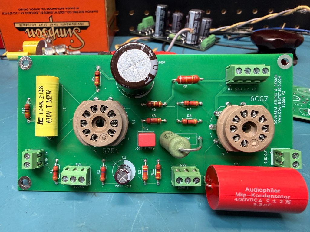
Transformer Selection
If you’ve followed my previous projects, you know how much I enjoy experimenting with transformers. I wanted to leave plenty of room for that with this design.
Input Transformer
A microphone input transformer in the range of 600Ω:10k–50kΩ is a good starting point. Some options worth exploring include:
- Altec 4722
- UTC A-11
- Vintage Triad, Freed and ADC transformers
- Modern offerings from UTM, Cinemag, Jensen and Sowter
A higher step-up ratio provides additional voltage gain before the signal reaches the first tube, while a lower ratio can provide more input headroom.
Output Transformer
I recommend starting with a 10k–15kΩ:600Ω output transformer. The UTM3515 and Edcor WSM15K/600 are two readily available modern options. You could also leverage the Altec 15095.
Because the output stage is capacitor-coupled, a gapped output transformer isn’t required, opening up plenty of vintage and modern possibilities.
Experimenting with different transformer combinations is a great way to give each build its own personality.
Power Supply Requirements
The DB-15666 requires an external high-voltage B+ supply and a 6.3V heater supply.
| Supply | Recommended specification per channel |
|---|---|
| B+ | Approximately 290V DC under load |
| B+ current capacity | 20–30mA design allowance |
| Heater voltage | 6.3V DC preferred; AC also supported |
| Heater current capacity | 1.5A or greater |
| Heater elevation | Recommended, based on measured cathode voltages and tube ratings |
Proper filtering, grounding and heater referencing are particularly important for keeping noise levels low and ensuring the cathode follower operates within its heater-to-cathode voltage limits.
I’ve also developed a standalone Downbeat tube power supply PCB that will be available alongside the DB-15666. It’s designed to be a flexible power supply solution for this preamp and other DIY tube audio projects.
Build Your Own DB-15666
I’ll be making both the DB-15666 audio PCB and the Downbeat tube power supply PCB available through my Downbeat Studio & Design store on Reverb.
I’m also making the schematic and bill of materials freely available, including sourcing links to Mouser and Amplified Parts.
Project Resources:
- DB-15666 Schematic (PDF)
- DB-15666 Bill of Materials
- DB-15666 Audio PCB on Reverb
- Downbeat Tube Power Supply PCB — Coming to Reverb
Safety note: This project involves potentially lethal voltages and is intended for builders experienced with high-voltage tube equipment.
I’m excited to get these boards into the hands of other builders and see what transformer combinations, tube selections and modifications people come up with.
Thanks again for following along. There are several more designs in the works that I’m looking forward to sharing.
-James


Leave a Reply