
If you’ve followed some of my previous preamp builds, you’ve probably noticed that I like to incorporate a stepped input pad. It’s a simple and inexpensive addition that makes a microphone preamp much more versatile, particularly when working with high-output microphones or driving vintage circuits.
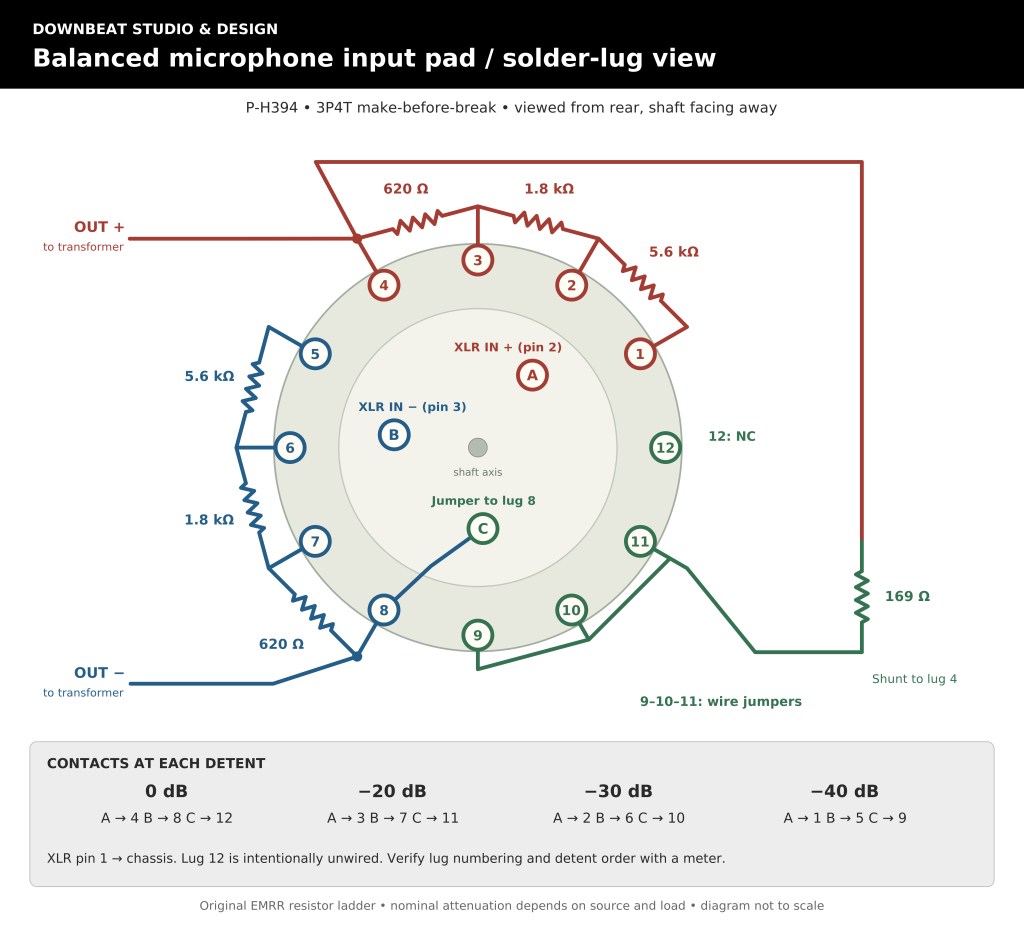
This particular design comes from EMRR over at GroupDIY. I’ve used it in several builds and wanted to share a cleaner schematic and point-to-point wiring diagram to make assembly a little easier.
The circuit uses a 3-pole, 4-position rotary switch and seven resistors to provide four attenuation settings:
- 0 dB – No attenuation
- −20 dB
- −30 dB
- −40 dB
The design maintains a balanced signal path and completely removes the shunt resistor when in the 0 dB position.
Parts needed:
- 1 × 169 Ω resistor
- 2 × 620 Ω resistors
- 2 × 1.8 kΩ resistors
- 2 × 5.6 kΩ resistors
- 1 × 3-pole, 4-position rotary switch
I recommend using 1% metal-film resistors to maintain good balance between both sides of the circuit.
This is a great little circuit to keep in your toolbox, whether you’re building a new microphone preamp or adapting vintage broadcast equipment for studio use.
Thanks again for following along, and happy building!


Leave a Reply